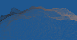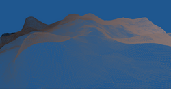
PROCEDURAL PLANETS
Generating Real Scale Planets in OpenGL
For my senior project and research at Cal Poly, I worked on the implementation of a program to generate real scale procedural planets using OpenGL. The project was done in association with Dr. Christian Eckhardt and the Cal Poly Mixed Reality Lab.
The immediate issue when discussing the generation of a truly real scale planet comes down to the limitations of the computational accuracy of modern computers. Even double precision floating point numbers only boast an average of 16 units of precision, and certain calculations needed for this project simply require more. To achieve this I used TTMath, a C++ library that allows the use and computation of quadruple precision floating point values.


CALCULATE SURFACE POINT
This function constitutes one of the main problems to solve and challenges to overcome in this project. To generate a mesh that represents the surface of the planet I first had two points on that surface with which to construct it. Using five predetermined constants I was able to accomplish this.
With the position of the camera, the planet's center, and planet radius I was able to calculate the surface point centered between the camera and the planet's center. However in addition to the center point I also had to find the four points that make the middle square of the mesh.
To do this I first had to decide how large each of these squares would be before generation. In the case of my renders each side of the square equaled the circumference of the planet divided by 100, meaning each "ring" of squares around the planet would be composed of 100 squares. So because I knew the size of each square I could calculate the diagonal length from the square's center to each of its corners. From here I could use the adjacent function to find the missing point of the triangle formed by the center point (known), planet center (known), and corner point (unknown). The arguments in this case would be: π / 4, the center point, and the diagonal length from the center the corner of the square.
I used π/4 because finding the missing triangle point in 2 dimensions is relatively easy, but in a 3 dimensional example such as this that point can lie anywhere on a circle. By superimposing a square on this circle I was able to find that π/4 is the angle on which the corner of the square intersects the circle.
This function is the foundation of my project and is used throughout the generation of the mesh to find additional points adjacent in the lattice (further described in the next section).


GENERATE MESH
By repeatedly using calcSurfacePoint() I was able to find every point in the mesh by building it out from the four corners of the center square. I first created a base lattice using π/2 as the theta for the offset along the circle. Then filled the lattice out with repeated calculation with a theta of 0.
Additionally it became useful to calculate the extreme points centered on each side of the mesh, and expand them outwards as the mesh grows.
While this method works, the problem that arose is that due to the length of this process it becomes very inefficient as the mesh grows.
GENERATE MESH CONT.
When the mesh consists of only a few squares the above process works fine. However the goal was to eventually generate an entire hemisphere of the planet as the camera continues to zoom out. With our approximation of 100 square rings that would mean the mesh we would need to generate would be 50x50 squares!
To solve the problem I developed a method to cut down the amount of squares that need to be calculated to 1/4 of the original mesh by only generating the mesh's upper quarter and mirroring it across the vertical and horizontal axis that divide it. By doing this you only have to find the normals of the triangles formed by the camera position, planet center, and either northern (horizontal) or western (vertical) extreme points of the mesh. From there some simple arithmetic can be used to mirror the point to its corresponding spot on the other side of the mesh.
 |  |  |
|---|---|---|
 |  |

Noise Generation
To generate terrain for the planet I used a noise function. Usually one could simply use the random number generators that come with C++, but in this case I wanted to generate these random values on the GPU so they can be used in tandem with tessellation (see below). This is further important because as the mesh rotates with the camera along the planet's surface, noise generation on the CPU (where the mesh is originally created) would result in the same terrain across the entire planet's surface. After generating the random value, it is used to offset a point on the mesh along the vector formed between the planet and the point, creating the terrain.
Noise function show courtesy of Dr. Christian Eckhardt.
Tessellation
To allow for a detailed terrain without needed to generate a mesh with a high polygon count on the CPU I utilized tessellation. In practice tessellation subdivides patches of geometry as determined in the Tessellation Control Shader stage of OpenGL's rendering pipeline. By sacrificing the detail of distant terrain, I am able to attain a high level of detail on geometry close to the camera, without a noticeable loss in performance. Furthermore, the noise function discussed above can be utilized in the Tessellation Evaluation Shader stage to add noise to all the subdivisions created through tessellation, not just the control points input from the CPU.
Below are examples of the power of tessellation where a relatively simple mesh is drastically transformed. The images range from no tessellation, to maximum tessellation.
 |  |  |
|---|---|---|
 |  |  |
 |
FUTURE WORK
While the original purpose of this project is complete there is much that can be done to improve and polish it. Moving forward I have plans to work on the following and more:
Atmospheric Scattering
Day & Night Cycle
Biome Generation
Further Mesh Simplification and Culling
Check back here for updates!
